WB
Equipment
WB Hydraulic & Pneumatic Jacking Systems

Supplier of Hydraulic and Pneumatic Jacking Systems for Jacking, Hoisting, Lifting & Moving.
Tel: 866-522-5464 Email:

THE RIGHT TOOL MAKES ALL THE DIFFERENCE

If it has to be moved, raised or lowered

and you don't know how… - we do!

VIEW MORE : Freyssi Flat Jacks

Freyssi Flat Jacks

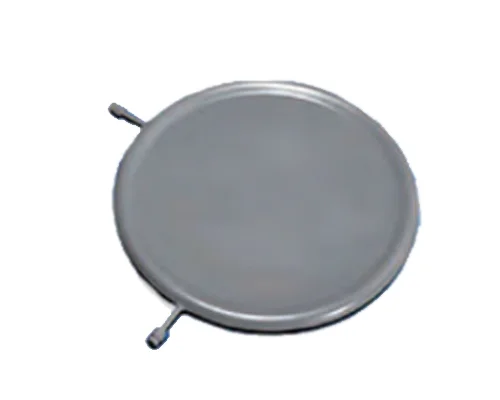
Freyssi Flat Jacks are simple, practical devices for the civil or structural engineer wherever the application or control of large forces is required. They are frequently used in the solution of unforeseen problems such as in remedial measures or structural additions.

They are as often used in new constructions in which they form part of the structural concept.

Freyssi Flat Jacks

View our YouTube Channel

Freyssi Flat Jack

Detailing Guidelines

  • Bearing Area – The whole surface of the flat jack thrust plate must bear upon a jacking surface. Local stiffening, distribution steel or concrete may be necessary.


  • Access Gaps – The selection chart shows the thickness and minimum access gap requirements which must be provided. If the full travel of the jack is required then packing shims must be fitted to fill any remaining space before inflation.


  • Tandem Jacks – Where the required jacking distance exceeds the travel of a single jack they may be stacked one on top of another and then inflated in sequence. Only the larger sizes of flat jacks may be stacked more than two high.


  • Sheer Resistance – Flat jacks must not be subjected to shear loads. Where necessary the flat jack must be protected from shear forces by housing in a shear box or by another means.
    Inlet/Vent Positioning – Flat jacks can be made with suitable inlet positions where access is especially difficult.


  • Oil-Resin Transfusion Jacks – When jacks are to be oil inflated and later transfused with epoxy resin, they are manufactured with an internal pipe to ensure satisfactory oil displacement. This requirement should be specified at the time of detailing.


  • Safety Packs – It is frequently advisable to make provision for safety packs when temporary oil flat jacks are intended to be in position for extended periods and at risk from mechanical damage from other activities in the jacking area


  • The flat jack consists of a mild steel capsule, circular in plan, with a cross section that is initially dumb-bell shaped. The dished portions are fitted with ground steel thrust plates before the jack is placed between the surfaces to be jacked apart. When the jack is inflated with a liquid the hydrostatic pressure is transmitted by the flat portions of the capsule through the thrust plates while the toroidal rim of the flat jack deforms to allow the flat faces to move apart.


  • The maximum operating pressure is only 150 bar (2,200psi). Flat jacks thereby exert low bearing pressures on the jacked faces.


  • The maximum recommended opening stroke of a flat jack is equal to the depth of the toroidal rim – about 25mm (1in).
    Two pipe connections are welded into the jack rim usually at 90 degrees to one another. One provides the inlet for inflation and the other serves as a vent during filling and is subsequently capped off.
  • The flat jack consists of a mild steel capsule, circular in plan, with a cross section that is initially dumb-bell shaped. The dished portions are fitted with ground steel thrust plates before the jack is placed between the surfaces to be jacked apart. When the jack is inflated with a liquid the hydrostatic pressure is transmitted by the flat portions of the capsule through the thrust plates while the toroidal rim of the flat jack deforms to allow the flat faces to move apart.


  • The maximum operating pressure is only 150 bar (2,200psi). Flat jacks thereby exert low bearing pressures on the jacked faces.


  • The maximum recommended opening stroke of a flat jack is equal to the depth of the toroidal rim – about 25mm (1in).


  • Two pipe connections are welded into the jack rim usually at 90 degrees to one another. One provides the inlet for inflation and the other serves as a vent during filling and is subsequently capped off.


  • Known Forces
    – Precise Control
    – Low Height For Limited Access Situations
    – Low Bearing Stresses
    – Out Of Parallel Tolerance  
    – Between Jacking Surfaces
    – Temporary, Removable Jacks
    – Permanent, Sacrificial Jacks
    – Structural Lifting
    – Underpinning
    – Control Of Thrust Forces
    – Maintenance Of ConstantThrust 
    – Adjustment Of Support  Reactions
    – Pretressing
    – Structural Pre-Loading
    – Loading Of Seismic Isolators
    – Arch De-Centering
    – Control Of Settlement
    – Measurement Of Forces
    – Weighing Of Offshore Structures
    – Permanent Shimming
Recently Viewed Products
No Posts Viewed
Monostrand Stressing Jacks
Post Tensioning/Monostrand Stressing Jacks consist...

Call for Information: 866-522-5464 or Email:

Share This Product to Social Media

Subscribe to Our Newsletter for new news items as they appear

Please Complete the Form

* indicates required